Review Article - (2022) Volume 10, Issue 7
Development of an Intruder Detection with Alert System Using Wireless Technology
Aluko Oluwadare Abiodun*,
Babalola Abayomi Donald and
Oyebiyi Adewale Julius
Department of Computer Engineering, The Federal Polytechnic, Ile-Oluji, Ondo State, Southwestern, Nigeria
*Correspondence:
Aluko Oluwadare Abiodun, Department of Computer Engineering, The Federal Polytechnic, Ile-Oluji, Ondo State, Southwestern,
Nigeria,
Email:
Received: 19-Apr-2021, Manuscript No. IPACSES-21-8219;
Editor assigned: 21-Apr-2021, Pre QC No. IPACSES-21-8219(PQ);
Reviewed: 05-May-2021, QC No. IPACSES-21-8219;
Revised: 10-Oct-2022, Manuscript No. IPACSES-21-8219(R);
Published:
17-Oct-2022, DOI: 10.36846/2349-7238.10.7.31
Abstract
This research work will help in providing the level of security in an enclosed area to prevent or disturb
attacks; this is done by keeping tracks of access information very convenient for the user to monitor
the security of the properties. Conglomerate in the world population with in commensurate
employment opportunities and pressures of a complex society, which among others include
incidences of human intrusion, burglaries and crime in private and public places are on the increase at
homes, banks, shopping malls, schools, offices, etc has become issue of concerned and worrisome in
Nigeria. Thus, there is need to design a home security system which can detect an intrusion via sensor
and trigger alarm, however, user who is away from home cannot get immediate notification of alarm
incident, a Global System for Mobile communication (GSM) with wireless technology based Security
system has to be incorporated to overcome the problem. This dissertation presents a design, and
implementation of a security system that triggers an alarm upon the detection of an intruder and
sends alerts via a SMS to whoever is in charge or security personnel. The system integrates sensor via a microcontroller such as Passive Infrared (PIR) sensor to detect an intruder and sound an initial
warning for 30 seconds while awaiting the user response (system deactivation) in case of false
intruder. Upon no response clearly indicates true intruder and the system eventually trigger an alarm
and sends an (SMS) Short Message Service alert (predefined message which is embedded within
microcontroller) to the user or security personnel through GSM module. The 4 x 4 matrix keypad is
used to give command and the password to the Micro Controller Unit (MCU), which enables the MCU
to verify the input from keypad with stored password to interface with peripheral device, upon the
input of the correct password, the user, can only make the system activated or deactivated. The
system used of PIR sensor, Peripheral Interface Controller (PIC) microcontroller, and GSM modem and
hand phone as main components. The Security System employs GSM applications as a major wireless
technology as to better performance of mobility, flexibility and ease installation. The developed
system was demonstrated and performed on Proteus software for efficiency and the design was
applied to a prototype home, when the intrusion detected with twenty five (25) attempt of
“intrusion,” message received at user’ hand phone and evaluation of developed system produced
values 0.8974, 0.9, 0.994 and 0.013 for specificity, sensitivity, accuracy and standard error delay time
respectively. The research recommended an implementation that reduces the delay time and increase specificity, sensitivity and accuracy through the power supply. The implementation of GSM
modem technology is function to improve the security system by sending alert message to user as
he/she is away from home. The advantages of this security system are its high security level, low cost
and ease of use.
Keywords
Micro controller unit; Peripheral interface controller; Short message service; Global system
for mobile communication
INTRODUCTION
Security is the condition of being protected against danger,
loss, and criminals. Individuals or actions that go or act
against the general rules of protection are responsible for the
breach of security. Security can also be seen as: A condition
that results from the establishment and maintenance of
protective measures that ensures a state of inviolability from
hostile acts or influences, with respect to classified matter,
the condition that prevents unauthorized persons from having
access to official information that is safeguarded in the
interests of national security, measures taken by a military
unit, an activity or installation to protect itself against all acts
designed to or which may, impair its effectiveness. The issue
of security threat (assassination, herdsmen killing,
kidnapping, and theft) around country, Nigeria. Many houses,
banks and schools are burgled mainly by means of illegal
entry, such as breaking of a window or entrance through an
unlocked door or an open window. Some common security
sensors that are used to indicate opening of a door or window
or to detect motion via Passive Infra Red (PIR). Many modern
alarm monitoring services allow users to access their home
security system online via the internet. They can check the
status of their system, and even view video of their home if
they have installed surveillance cameras, buhur and recently,
in India, a video clip system has developed a way to transfer
the video stream to a mobile phone through ethernet from
PCs. A new kind of wireless image system provides users with
the image information by means of a Multimedia Message
Service (MMS). After so many reviews main focus were given
on GSM based home security. It is very easy to install and it is
cost maintenance effective. Basically, it’s installed over the
entry doors and that doors consist of (PIR) motion sensor
which is connected to PIC. Signals will generate via relay and
sends it to PIC18F2455 Microcontroller and action takes place
according to piece of code written in the chip and GSM
module sends message to owner's phone. The aim of this
work is to fill this gap by presenting a system with a high
security level and a low cost. This Home Mobile Security
System (HMSS) solves the problem related to the false alarms
found in other systems by integrating two sensors into one
unique system [1-5].
Statement of the Problem
Rapid growth in the world population with in commensurate
employment opportunities and pressures of a complex
society, which among others include incidences of human
intrusion, burglaries and crime in private and public places are
on the increase at homes, banks, shopping malls, schools, offices, etc has become issue of concerned and worrisome in
Nigeria. Thus, there is need to design a home security system
which can detect an intrusion via sensor and trigger alarm,
however, user who is away from home cannot get immediate
notification of alarm incident, a low cost GSM based scurity
system has to be incorporated to overcome the problem. This
system will provide a real time security system that will trigger
alarm that performs visual and audible responses via buzzer
and sending alert via SMS through GSM network. The user
can therefore; monitor and get an update of home status
anytime, anywhere provided the availability of the GSM
network or signal.
Literature Review
A security system is defined as to detect intrusion,
unauthorized entry into a building or a protected area and
deny such unauthorized access to protect personnel and
property from damage, loss or harm. Security systems are
mainly used in residential, commercial, industrial, and military
properties for protection against burglary (theft) or property
damage, as well as personal protection against intruders.
History of Intrusion Alarms
Intrusion alarms are as old as the silicon age. The truth is, the
concept of an alarm system is one that was invented long
before now. For thousands of years man has used animals,
most notably the dog, to guard and alert people of anyone
trying to tamper or steal his valuables. In the middle ages
large gongs were used to warn a population of impending
doom or large bonfires lit to warn of imminent invasion,
showed a solenoid struck a gong when a trip wire was
disturbed. Although his alarm system is nothing compared to
today's offerings it was positively received in its day. These
early alarm systems continued to make use of simple
electrical circuits and relays. This technology allowed smaller
units integrated with microwave and ultrasonic motion
sensors along with features such as entrance and exit delays
to be introduced. A central controller based home security
system looks to improve the security of the homes in a locality
by combining many homes into a security network with a
control node dedicated for each locality depending on the
number of users. These control nodes are controlled by a few
central or chief control nodes with considerably high
processing power. The security system described called Home
Security System on Intelligent Network (HSSIN), uses such a
central controller based approach. The system lacks modern
security parameters [6-9].
A central controller based security system has its own unique
challenges which include:
• All or most homes in the neighborhood have to join in for
the approach to be cost effective and successful.
• The main question has to be considered here is who
controls or has access to the central controller and its
data?
The central controller will be able to know about a home’s
intimate and private information from the data at its disposal,
like if a home’s room heater is on, or if an inhabitant in a
home is taking a shower. This raises serious privacy concerns
security system alerting via SMS was designed using vibration
sensor, PIC16F877 microcontroller, and GSM modem and
hand phone. This system was designed to detect single
intrusion, which can be classified as point detector as it can
only indicate intrusion at a specific point. Showed the
implementation of a web based and home controller security
system. The architecture of a web based system as shown in
Figure web server governs the interfaced webpage that allows
user to control the system. The monitoring of home condition
is done over web browsers through the use of laptop,
Personal Digital Assistant (PDA) or internet enabled mobile
phone. Laptop is connected to internet via wired local access
network or Wireless Local Access Network (WLAN). PDA gets
connected to internet via WLAN. Internet enabled mobile
phone is connected to an internet service which is provided
by a mobile service company. When a sensor detects
abnormal incident, an alert message is sent to user through
web page. The house owner gets to confirm the alarm after
observing home condition for true abnormal incident through
installed camera. Web based system makes use of high
cost devices such as personal computer, laptop or PDA (Figure
1).

Figure 1: An illustration of web based home security system.
Nurmarizah developed a security system that will alert the
user through SMS. Throughout the system, user will be
alerted if intrusion occurred within compound area of
attached sensor. This system used one sensor, microcontroller,
and GSM modem and hand phone as main components.
Security system applied is fully wired technology.
Implementation of GSM modem technology is function to
improve the security system by sending alerting message to
user as they are away from that compound area. The system
was designed to detect theft, fire leakage and alarm remotely
but the system cannot alert the owner remotely. There is lack
of flexibility, scalability in the system, high cost implication for
maintenance and limitation of distance location proposed a
security monitoring system based embedded and Zigbee. A
combination of Zigbee and GSM, PIR vibration and magnetic
sensors installed at window and door along with Zigbee end device to the present of unauthorized person in a restricted
area. The limitation of the work was that it incurred access
delay, and the technology used Zigbee range 50 m only and
data transmission rate was very low proposed a home
automation security system called smart eye using General
Packet Radio Service (GPRS). Smart eye also uses a central
controller, to which many individual home controllers were
connected. The system was a real time home automation and
monitoring system. The system alerts the homeowner by
mobile phone using GPRS, and the user can view the home
using live camera feeds. The system uses a rabbit core module
to connect an electrical appliance in the home to the home
system, usually a PC. Each home system is connected to a
central server. Rabbit core has an IP address, so each device
connected to it can be identified and operated via mobile
phones using GPRS. The user sends device management
commands to a central server. The home system reads the
command from the central server, called home polling, and
makes the changes needed to a device. When a device
changes state, the home system, usually a PC sends the
change of state of the device to the central server. The user’s
mobile will read the change from the central server, called
mobile polling. The mobile user is provided with a home plan
and places where each piece of equipment is kept in their
home. Understanding the context of a particular action by the
user could go a long way in improving a home’s security
defined context as any information that can be used to
characterize the situation of an entity. An entity is a person,
place, or object that is considered relevant to the interaction
between a user and an application, including the user and
applications themselves. In a context aware home automation
system, the system tries to be aware of the context in which a
user makes a decision. Predicting the location of a user inside
the home adds to defining the context discussed different
techniques for identifying the location of a user at home. This
works used of an infrared grid to accurately predict the
position of the user in the home, thus contributing to
improved security. But this grid of infrared sensors is difficult
to implement in a home environment. The work also
discusses the use of badges to identify the location of
inhabitants inside the home. This could significantly improve
security, but it is inconvenient for the user. Moreover,
inhabitants can be careless in their home and misplace these
badges, which lead to confusion in the system. Another
method mentioned in the work is static object checking. It
identifies an inhabitant’s location by checking to see if
someone is in the proximity of a static object. This method
limits the flexibility of the environment, and if someone
moves or changes the position of these static objects, it will
be very confusing to the system explained in detail why
contextual sensing is difficult. The human aspect or human
behavior is very difficult to predict or reason out. People tend
to be unpredictable or unreasonable at times. Unlike
computers, human can improvise, and tend to make impulsive
decisions about their context. Context aware computing raises
a serious question of user privacy. With context aware
computing, the system has even more intimate information
about the user also worked on home automation system
using bluetooth that can be accessed remotely through GPRS.
The researchers used a cell phone equipped with Bluetooth
connectivity as a host controller and a GSM modem that
provides Internet connectivity. Home devices were fitted
with bluetooth communication adapters so that they can
communicate with the host controller phone via Bluetooth.
The work discusses remotely controlling and updating host
controller phone via Bluetooth. The paper discusses remotely
controlling and updating home devices along with fault
diagnostics and detection. The work also talks about providing
an electronics user manual on the phone using bluetooth and
internet [10-14].
Disadvantages of using bluetooth for home
automation include:
• Bluetooth has a maximum communication range of 100 m
in ideal conditions. More than what may be needed in a
home environment.
• Bluetooth communication has comparatively high power
consumption, so the batteries of devices need to be
frequently recharged or replaced.
• Bluetooth technology has advanced and improved to
Bluetooth Low Energy (BTLE), which provides the same
range of communication. However, it has serious security
concerns such as eavesdropping and weak encryption as
identified by Ryan.
• Bluetooth communication should only be used on
occasions where there is a need for quick short lived
network communication with little concern for security.
Bluetooth looks like an attractive communication technology
for creating smart homes. It is cheap, easy, and quick to set
up. People are already familiar with the technology. The
hardware required for establishing bluetooth communication
is readily available. And the technology also provides the
necessary bandwidth for operation in homes discussed
Internet or IP protocol based communication in home
automation systems; this is always a popular choice among
researchers. The internet is easily scalable, flexible when it
comes to access and use, and very popular as a
communication method in today’s world, so the hardware
and the network required for access is readily available, offers
high bandwidth and very low communication cost, and
devices can connect to and disconnect from the network
easily. These are some of the features that make the Internet
such an attractive choice for researchers.
Methodology
This section describes the methodologies used for the design
of the hardware and software parts. The main hardware parts
are the motion sensors and how it is interfaced to the
microcontroller and the GSM interface. The model and
methodology, considerations/specifications of the intrusion
detection system, its functional components and the
development stages and modes of operation of the software
application developed for the hardware, were discussed
[15-17].
System Design Steps
The design steps involved in the development of the system
was such that the system aimed to operate off a 12 volts
power supply system. The system is an intruder alert system
with at least one programmable integrated circuit, in this
case, PIC microcontroller will be used which is programmed
using micro pro and easyPIC6. The microcontroller is
programmed to receive signal from the PIR motion sensor
once it senses or detect infrared from an intruder and activate
the alarm unit inculcated in the complete system and send
SMS alert to the owner via GSM module. The program will be
such that when an intruder is detected, the system allow for
30 seconds deactivation period in case of false intrusion. The
period is to allow the owner to input the password for system
deactivation, otherwise the system triggers the alert system.
This intrusion security system consists of mechanical,
electrical, and electronic components, which are integrated to
complete the system design, as follows:
• Microcontroller
• PIR motion Sensor
• GSM module
• Crystal oscillator
• Comparator (LM358)
• Transistor (BC547)
• Light emitting diodes
• Liquid crystal display
• Resistors
• Capacitors battery (12 V)
• Voltage regulator (LM7805)
• Buzzer
• Keypad
Hardware Implementation of the Design
Hardware of the system consists of the
PIC18F2455 microcontroller, GSM module, sensor, proximity
sensor and GSM phone, Buzzer and other components
which its design was carried out on the manufactured
breadboard mainly surface mounted components, in
system programmer and relays to control the appliances.
The sensor unit comprises of an integrated circuit module
such as PIR motion sensor which is placed in front of the
design. This integrated circuit is powered using 5 volts dc
power source. A signal is sent to the microcontroller each
time infrared is detected from the intruder’s body and the
necessary actions are taken based on the program written to
the microcontroller. The PIC will be thus programmed. The
power source was obtained from a 12 volt battery. The
microcontroller and other digital integrated circuit use 5 volts
for their operation and as such, a voltage regulator will be
used to regulate the 12 volts power supply to 5 volts for use
by the circuit. The block diagram of the design is shown in Figure 2.

Figure 2: Showing the block diagram of an intruder detection
and alert system.
The Block Diagram Shows how the Following Units
were Integrated
• Detection unit
• Microcontroller unit
• GSM Module unit
• Alarm unit
• Display unit
The power supply section is very important for all electronic
circuits. The system requires 5 volts dc. This voltage level will
be obtained from the 12 v battery. The 12 v is stepped down
by to deliver a secondary output of 5 V, 1 A. The 12 v battery
output is rectified by a full wave rectifier comprising diodes
D1 through D2, filtered by capacitor C3 and C4 regulated by
IC7805 (IC) Capacitor C3 bypasses the ripples present in
the regulated supply. The power supply schematic is shown Figure 3.

Figure 3: Showing the intrusion detection.
Detection unit: As shown in the Figure 4 of an infra-red
transmitter/detector, the transmitter transmits pulse signal at
a frequency of 36 KHZ to the receiver in the line of sight
arrangement. The receiver receives this pulse signal at an
operating frequency of 36 KHZ. This pulse signal made the
infra red receiver pin high or at logic 1. Once this pulse is
broken, it made the receiver output low. This low signal is
then sent to the input pin of the microcontroller which made
the microcontroller perform the predefined task indicating an
intrusion. The 10 kΩ potentiometer is used to set a reference
voltage for the comparator. The inverting input of LM358 is set
at the middle of the 10 kΩ potentiometer such that the
reference voltage is giving as:

The high voltage level output of 3.3 v from PIR motion sensor
is fed to the non-inverting input of the comparator LM358,
which compares it with the reference voltage of 2.5 v fed to
the inverting input of LM358. As long as the 3.3 v output from
the PIR sensor is greater the reference voltage of 2.5 v, the
comparator outputs a logic one (5 v) to the PIC18F2455.
PIC 18F2455 Microcontroller unit
The control module was built with the microcontroller IC. The
central controller is the PIC 18F2455 microcontroller. The
PIC18F2455 microcontroller hardware circuit is usually a
lexible, low power, high speed FLASH/EEPROM using CMOS
technology.
PIC18F2455 microcontroller features 128 bytes of EEPROM
data memory, self-programming, reset resistor 8.2 KΩ to 15
KΩ, an ICD, 2 comparators, 5 channels of 10 bit Analog to
Digital (A/D) converter.
The 2 wire inter integrated circuit (I2c) bus and a
Universal Asynchronous Receiver Transmitter (USART) was
used, PIC microcontroller datasheet.

Figure 4: Control circuit design.
GSM Modules Unit
The GSM modem unit is built using the SIMCOM SIM 900
modem that specialized for microcontroller and support
GPRS technology for satellite navigation. This module takes
care of all GSM/GPRS based communication requirements as
well as provides live GPRS data. The GSM Module SIM900A
can be directly interfaced with PIC Microcontrollers,
through the three lines; TX, RX, GND. The transmit signal of
the serial port of the microcontroller is connected with the
transmit signal (TXD) of the serial interface of GSM
Modem while receive signal of the microcontroller serial
port is connected with receive signal (RXD) of serial
interface of GSM modem (Figures 5 and 6).

Figure 5: Shows how the GSM is interfaced with PIC18F2455
microcontroller.

Figure 6: Showing the interfacing GSM module with
PIC microcontroller.
The Display Unit
This display unit used for the design is Liquid Crystal Display
(LCD) because of its ability to display numbers, character,
graphics, and ease of programming for characters and
graphics and low power consumption. The 2 x 16 character
LCD has two rows of 16 characters each. The display
receives ASCII codes for each character at D4 to D7 which is
connected directly to the 4 PORTB pins of the
PIC18F2455 microcontroller. To initialize the LCD, the Register
Selects (RS) line must be set to logic 0. The 8 bit code for
each ASCII character is sent in two halves; high nibble first,
low nibble second. Although this makes the software only
slightly more complex, it saves on I/O pins and allows the
LCD to be driven using only six lines as shown in Figure 7.

Figure 7: Liquid crystal display to PIC 18F2455
microcontroller interface.
The Design of the Buzzer Unit
The buzzer is connected to a 12 volts supply and connected via a BC547 transistor to the ground. The base of the
transistor is connected to the microcontroller through a
current limiting resistor (10 K), the Figure 8 shown the circuit
diagram of buzzer unit.

Figure 8: Circuit diagram of the buzzer unit.
Complete Circuit Description
The 9 V power supply was used and connected to the voltage
regulator which was used to step down the voltage to the
required voltage for the microcontroller that ranges from 4.5 v
to 5.5 v. The voltage regulator has three legs, the irst leg was
connected to the 9 V batteries on positive terminal, and
second leg was grounded and has to be connected to pin 8 of
the microcontroller. The last leg was connected to
microcontroller pin 7. A 10 KΩ resistor was used and
connected to pin 1 through pin 7 of microcontroller on port A.
The two capacitors of each 22 pF were connected to 12 MHz
crystal oscillator in parallel connection with the
microcontroller on pin 9 through pin 10 respectively. This was
to synchronize the operation of the microcontroller and other
electronics on the board. In design, two sensors were used,
the sensor consist of three pins, each of its irst pins connected
to the power supply, second pins (out) connected to
microcontroller on port C, pin 12 through 13 and the last pins
were grounded. The pin 1 of Microcontroller is described as a
master clear (MCLR) which is used for reset button in 30
second time delay. The LCD with 16 pins connected pin 4 (RS)
pin 6 (EN) and the last 4 pins of the 8 bit ASCII code: D4, D5, D6
and D7 with microcontroller at Port B pins: 26, 25,24,23,22,
and 21 which are data bus respectively. While pins: 1 (Vss), 3
(Vee), 5 (R/W) connected in series with pin D0-D3 alongside
with 10 KΩ resistor were grounded, Pins 15 and 16 were for
the backlight of the LCD and only pin 2 connected to the
power supply, pin 8 and pin 22 on microcontroller were also
grounded. The keypad has 8 pins in which pins 0-3 were for
rows and pins 4-7 were for the columns (A), they were
interfacing with the microcontroller on port assignments. The
GSM module consists of 3 pins RXD and TXD connected to
microcontroller on pin 11 through pin 12 respectively. Speaker
or buzzer connected with the microcontroller on port B, pin 27
and through pin 28 respectively. PIR sensor of the design has
three pins in the pin (Vcc) was connected to power supply and
second (out) was connected to pin 12 of M/C. at port C, while
the last pin of the sensor was grounded. The PIC
microcontroller transmits and receives data with respect to
clock pulses. The physical implementation of the design was
carried out on the manufactured breadboards using mainly
surface mounted components. The component was then
soldered into the respective component slots using a 30 W
soldering iron as shown in Figure 9.

Figure 9: Showing the circuit diagram of intrusion security
system via SMS.
Operation of Intrusion Security Systemv ia SMS
In the designed system, once the system is powered on and
activated with the activate button, the system starts
monitoring the environment for an intruder as shown in the Figure 10 below. When the motion sensor (PIR)
detects a movement of an intruder, system sounds an
initial alarm expecting the intruder to deactivate the system
with the set password in case of false intrusion as shown Figure 11 below. If the password is correct, the system is
deactivated and continues to monitor the environment as
shown in Figure 10. If the intruder did not input any password
within 30 seconds or if the password is incorrect, the system
sounds an alarm with the buzzer and displays the message
“intruder detected” on the LCD as shown in Figure 12. And
also an SMS will be send to a predefined number which
could be owner of the restricted area or security reaction
company via GSM module as shown in Figure 13. A keypad
was used to give commands and the password to the MCU to
enable only an authourized user has ability to activate and
deactivate the system. When the device is turned on, it
needs to be activated by pressing the push button, then it
will give only 30 seconds to allow the owner to safely exit
your home or sleep without triggering the alarm, within this
stipulated period of time, a status of green LED will blink. After
that, the status LED will stay on to notify you that the
program is in the alarm mode. In alarm mode, the
program will constantly monitor the input from the PIR when
motion will be detected. The reason for this short delay
before activating the buzzer is because it might be the owner who
might want to deactivate the alarm, 30 seconds is given to
reach the alarm and switch it off or deactivate it. Once the system
is deactivated, one have to press the push button again to
activate it and check it the status LED is on Figure 14.

Figure 10: System monitoring the environment for intrusion.

Figure 11: System requesting for deactivation password.

Figure 12: Intruder detected by the system.

Figure 13: SMS alert showing intruder detected.

Figure 14: External view of the intrusion detection and
alert system.
Results
The result of simulation ensures that the circuit worked at
properly. The practical implementation of simulated circuit
has been presented. In this circuit diagram PIC microcontrollers was the main components used
for controlling other devices (PIR sensor module, GSM
module, LCD display and buzzer). Among the controlling
devices, motion sensor was used as a sensor for determining
the present status of the system. PIR motion sensors were
placed at the entrance of the building where it is suitable to
detect within the range of 7 m. This signal which detects
intruder presence triggers the input of the microcontroller.
The owner may or may not be present will receiving the text
messages by providing the alert message “there is an
“intruder detected” or else the if the module is unable to
send the SMS this newly proposed method launch an
automatic alarm call to the concerned authority
regarding the corresponding information. The overall
working of the system is controlled by the mobile device.
The message gives the feedback following the
performance and display errors. The proper operation of
the sensor requires a warm time of 30 seconds as it
requires to the sensor according to the stable
environment. The connectivity is provided based on the PIC
microcontroller and then communicates with GSM module via the network. The sensor which generates the electrical signals
converts to GSM module using PIC microcontroller. The delay
time is important aspect regarding the message to user device
should be of fixed delay that was implemented through the
microcontroller programming code. The issue in this system of
receiving high output signals can be reduced to low by
programming of the PIC18F2455 as the PIC microcontroller
board has 14 digital input/output pins, USB connection, ICSP
header and reset button. It contains everything needed
support for system implementation. The system provides a
user interface as it interacts with the system. The PIR sensor
responsible for the detection of motion adjusts itself to the
infrared signature of its surroundings and keeps watching for
any changes. In the absence of motion, the LED indicator will
remain dim, and the program will continue updating the
surroundings. If the sensor detects movement, the frame for
motion detected will be the input frame to the process of
human detection, and consequently, the motion detection
indicator will light up. The result of the testing performed on
the implemented system. Total values of 760 seconds at
difference distance (m) were: 18, 17, 7 and 2 were obtained
for delay time, Td, Ta, Fd and Fa, respectively. The average
delay time was 30.4 seconds which reflects a percentage error
of 0.013. It is also noteworthy to indicate that the lithium
batteries used were getting weak and the batteries were
replaced twice, after the tenth (10) and the twentieth third
(23) attempts.
Parameters for Evaluating the Developed System
The monitoring system of this project consists of two sub
systems which are notification system and alert system. The
notification system enables the user to be notified any alarm
incident of home condition via SMS (Short Message Service)
which is done over GSM technology. Alert system performs
visual or audible responses through light emitting diode
display and buzzer or siren respectively.
The following parameters were used for evaluating this
developed system:
• False Detection (FD): This is the process whereby the
implemented system detects the presence of an intruder
but fail to trigger or send alarm and alert.
• False Alarm (FA): This is the process whereby the
implemented system does not detect an intrusion but mistakenly sends the alarm.
• True Detection (TD): This is the process whereby the
implemented system detects the presence of a true
intruder and the system sends or triggers alarm and alert.
• True Alarm (TA): This is the process whereby the
implemented system detects a false intruder and truly
sends the alarm and system been deactivated from
sending alert.
• Sensitivity (SE): The degree of response of the system to
correctly detect or identify a true intruder.
• Specificity (SP): The state of being specific for a false
intruder.
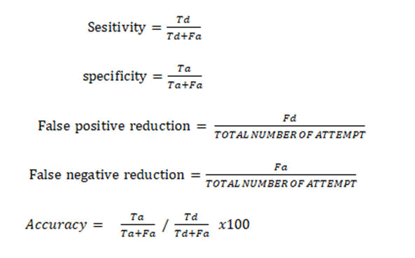
Accuracy can be determined from sensitivity and specificity
with the presence of prevalence (mean or total population) of
cases in the given time. This system performance better at 2-3
m and it was observed the system gave false alarm when the
battery of system weak and as well unable to send alert when
the intruder being detected at a very long distance but display
only alert via visual or audible responses. Visual responses
are indicated by light emitting diode and audible indicated by
buzzer or siren. Percentage accuracy measured SP/SE x
100=99.4%
Discussion
The prototype were designed and implemented. The results
obtained from the combination of various intrusions
detection system components and corresponding
constructions are evaluated and some observations were
made during the different stages of testing. Some distances
were taken so as to ascertain the workability of the intrusion
detection system. The best line of sight is about 300 cm the
distance from the developed system and the suspected
intruder. The percentage error reflected was due to internal
frictions within the security system mechanism. Specificity
(SE) of the developed system was 0.8947 (89.47%). This
implies the ability of the implemented home security system
correctly detect an intruder and trigger alarm and alert via GSM Technology. Sensitivity of the implemented home security system was 0.9 (90%). This indicates that the
implemented home security system was able to correctly
detect an intruder and trigger alarm and alert via GSM
technology to owner of the house. Nevertheless, the
recognition accuracy of the implemented home security
system was 99.4%.
Conclusion
The developed of an intruder detection and alert security
system gives good response to the motion sensor when it
detects intrusion at the restricted area. The result showed
that both the switch and the motion sensor attached to the
entrance performed adequately as expected. The entire
decision making was carried out with the aid of a PIC18F2455
microcontroller. One of the main feature of the design, it was
built with a time delay of 30 seconds to allow a false intruder
(i.e. if it is the owner), inputs the right password, the system
deactivates and continue to monitor the environment for
further intrusion. If it is a true intruder (i.e. unknown person
who does not know the password), and the person does not
input the password within 10 seconds or if the person inputs
the wrong password, the system sounds an alarm and sends
SMS to the owner or security personnel. The project exploits
the advancement in the technology of communication to
provide a comfort for users. Implementing this project in
every homes, implies improving the security of the home and
also bringing what goes on at home closer to the owner
anywhere at any time provided the GSM network is available
and well reduce burglary and theft. This project design
achieved all its targeted aims and accomplished its objectives
successfully.
Recommendations
For the purpose of future researches on this project and a
means of improving this project, it is recommended that:
• The future implication of the project is very great
considering the amount of and resources it saves. This
system can be used as a reference or as a base for realizing
a scheme to be implemented in other projects of greater
level including audio-visual camera by sending the
captured image to e-mail and cloud instantly.
• Further research work can include multiple PIR motion
sensors integrated with the system. This will ensure
multiple outlets monitoring of the environment and for
more effective security measure. This can be achieved if
the building or environment of the system is to be
installed is first accessed in order to ascertain the sensors
strategic location point.
References
- Aayush A, Joshi RC (2014) WSN and GSM based remote home security system. Int J Adv Res Comput. 4(1):107-115.
[Crossref][Google Scholar][Indexed]
- Agarwal N, Nayak GS (2013) Microcontroller based home security system with Remote Monitoring. Int J Comput Appl. 38-41.
[Google Scholar]
- Atukorala K, Wijekoon D, Tharugasini M, Perera I, Silva C (2013) Smart Eye Integrated solution to Home Automation, security and monitoring through mobile phones. Third International Conference on Next Generation Mobile Applications, Services and Technologies, Cardiff, UK. 64-69.
[Crossref][Google Scholar]
- Bangali J, Shaligram A (2013) Design and implementation of security systems for smart home based on GSM technology. Int J Smart Home. 7(8):201-208.
[Crossref][Google Scholar][Indexed]
- Bellotti V, Edwards K (2001) Intelligibility and Accountability. Human Considerations in Context Aware Systems. Hum Comput Interact. 16(2):193-212.
[Crossref][Google Scholar][Indexed]
- Bhavya J, Sakshi S, Varun K, Debarshi G, Suresh S (2013) Home monitoring and security system. Department of Information Technology SRM University Kattankaluthur Campus, Tamilnadu, India.
- Buhur U, Alkar AZ (2001) An Internet Based Wireless Home Automation System for Multifunctional Devices. IEEE Trans Consum Electron. 51(4):1169-1174.
[Crossref][Google Scholar][Indexed]
- Elshafee H, Hammed D (2012) Design and implementation of an Internet based Home Automation System using Wi-Fi technologies. Int J Comput Sci. 4:39-45.
[Google Scholar]
- Olarewaju IK, Ayodele O, Olukayode F (2017) Design and construction of an automatic home security based on GSM Technology and embedded microcontroller unit. Int J Comput Sci. 1(1):25-32.
[Google Scholar]
- Cheng dong W, Jun H, Zhongjia Y, Jiyuan T, Qiaoqiao W, et al. (2008). Research of Intelligent Home Security Surveillance System Based on ZigBee. Intelligent Info Tech App Workshops. 554-577.
[Crossref][Google Scholar][Indexed]
- Umar NB (2011) Security System Alert via SMS. Department of electrical/electronic, University of Malaysia.
- Nwalozie GC, Aniedu AN, Nwokoye CS (2015) Enhancing Home Security Using SMS based Intruder Detection System. Int J Com Sci Mob Com. 4:1112-1120.
[Google Scholar]
- Oyebola BO (2015) Microcontroller based motion detection alarm system using PIR (infrared) sensor. J Manag Sci Tech. 1(1): 44-49.
- Kodali RK, Jain V, Bose S, Boppana L (2013) IoT based Smart Security and Home Automation System. J Eng Res Technol. 5(1):312-320.
[Crossref][Google Scholar]
- Sang-Hyun L, J Lee, M Kyung-II (2013) Smart Home security system using multiple ANFIS. Int J Smart Home. 7(3):121-132.
[Google Scholar][Indexed]
- Shah J, Singh MBR (2014) Design and implementation of home automation security system using RF and SMS Technology. Int Conf Electron Commun Syst (ICECS). 3(2):1-6.
[Crossref][Google Scholar][Indexed]
- Shwaki F, Dessouki ME, Elbasiouny AI, Almazroui AN, Albeladi FMR (2015) Microcontroller based smart home with security using GSM technology. Int J Eng Res. 4(6):20-28.
[Google Scholar][Indexed]
Citation: Abiodun AO, Donald BA, Julius OA (2022) Development of an Intruder Detection with Alert System Using Wireless
Technology. Am J Comp Science Eng Surv. 10:31.
Copyright: © 2022 Abiodun AO, et al. This is an open-access article distributed under the terms of the Creative Commons
Attribution License, which permits unrestricted use, distribution, and reproduction in any medium, provided the original
author and source are credited.