Research Article - (2025) Volume 12, Issue 1
Research on Fuzzy-PID Switching Control of Electro-Pneumatic Servo System Based on Matlab-AMESim Co-Simulation
Myong Song Ryu*
Department of Science and Technology, KimChaek University of Technology, Pyongyang, North America
*Correspondence:
Myong Song Ryu, Department of Science and Technology, KimChaek University of Technology, Pyongyang,
North America,
Email:
Received: 20-Sep-2024, Manuscript No. IPBJR-24-21578;
Editor assigned: 24-Sep-2024, Pre QC No. IPBJR-24-21578 (PQ);
Reviewed: 10-Oct-2024, QC No. IPBJR-24-21578;
Revised: 04-Jan-2025, Manuscript No. IPBJR-24-21578 (R);
Published:
11-Jan-2025, DOI: 10.35841/2394-3718-12.1.132
Abstract
With the development of industrial automation technology, pneumatic position servo control systems are widely used using fast switching solenoid valves instead of expensive proportional valves or servo valves.
However, the fast switching solenoid valve has a bad effect on the position control characteristics due to its inherent nonlinear nature.
Therefore, it is necessary to use a suitable control method to compensate for the nonlinear behavior of the fast switching solenoid valve and to construct its accurate nonlinear mathematical model.
We constructed firstly an air, machine, electrical and electronic model of a fast switching solenoid valve using AMESim and, on this basis, propose a new nonlinear model of a fast switching solenoid valve controlling pneumatic servo position control system.
In addition, a Fuzzy-PID switching control system was designed by combining the advantages of PID control and fuzzy control. A control block was constructed using Matlab/Simulink control toolbox, and the dynamics of the system was simulated in conjunction with the above AMESim model to validate the method.
Since the absolute control error in Fuzzy-PID switching control method is less than 0.25 mm and the dynamic characteristics of the controller are good, the proposed model and Fuzzy-PID switching control method in this paper have significant effects on improving the Electro-pneumatic servo position control performance using fast switching solenoid valve and developing accurate pneumatic motion control.
Keywords
Electro-pneumatic servo system; Fast switching solenoid valve; Fuzzy–PID switching control; AMESim; Matlab/Simulink
Introduction
Distinct advantages, such as a high power-to-weight ratio, low cost, ease of maintenance, being environmentally friendly, safety in operation, and simplicity of design, have made the pneumatic systems an attractive alternative for hydraulic and electro-mechanical systems. Unfortunately, the pneumatic actuator is affected by high friction, dead zone (due to static friction) and dead time (due to air compressibility).
This nonlinearity makes accurate positioning of the pneumatic actuator difficult to achieve. As a result, considerable research has been done on the development of multi-position control systems in pneumatic actuators. The precise positioning and velocity control of pneumatic cylinders can be achieved by using servo proportional valves.
The principle of various types of servo valves and the general construction methods of pneumatic cylinder position control system using them are investigated. The pneumatic cylinder is used to achieve position control by using servo valves with improved characteristics by high-resolution encoders, and a method for designing position control systems considering the servo valve dynamics is proposed. In addition, some researchers have studied the method to obtain linear equations instead of complex nonlinear equations and to realize their control, since the mathematical model of pneumatic actuation system has strong nonlinearity. ShenglinMu studied the predictive fuzzy control method combined with neural network in pneumatic position servo system based on pneumatic pressure valve and validated the accuracy of the method by experiments [1]. Shibo Cai studied a PID system, designed a fuzzy-PID switching controller, and compared with conventional PID control [2].
Many such systems employ expensive servo-proportional valves and pressure sensor feedback loops, although successful. Studies have been carried out to develop fast, accurate and cheap pneumatic actuator systems using inexpensive switching valve instead of expensive servo valves. Noritsugu used the PWM method and the electronic valve to control the speed and position of the pneumatic cylinder, and Yang studied the characteristics of the PWM control in a fast switching solenoid valve.
Muto and Yamata also used the differential PWM method to control the hydraulic actuator. However, due to the limitation of the response time of the valve in the valves and its discontinuous switching and shutting, fine motion control is difficult [3-6]. So, a reasonable control method to overcome the nonlinearity of the fast switching valve and its nonlinear mathematical model were also investigated. SHIBATA proposed a fuzzy control method using a virtual reference generator and, on the basis of it, realized the positioning of a pneumatic vertical servo system using fast switching valve, validated the method by experiments [7]. Xiang Gao proposed a new adaptive fuzzy-PD controller, studied the adaptability of a fuzzy-PD controller in a typical nonlinear and time-varying pneumatic positioning servo control system [8].
Jakub T constructs a nonlinear mathematical model of the pneumatic position servo control system using proportional valves, designed a fuzzy PID controller by fuzzy logic toolbox of Matlab/Simulink software, and verified the accuracy of the proposed model and controller through simulation and experiments [9]. Ruibo Yuan constructs a linear mathematical model of the pneumatic positioning servo system using the pneumatic proportional valve, simulates the system control using AMESim and Matlab, and shows that the PID controller is stable, accurate and can overcome the nonlinearity of the pneumatic servo system to a certain extent.
However, in previous papers, a nonlinear model of the pneumatic servo system using the fast switching solenoid valve has not been proposed and its detailed simulation results have not been introduced.
Therefore, in this paper, a simulation model was developed by combining AMESim and Matlab/Simulink in a fast switching solenoid valve-based pneumatic position servo system The design process of the fuzzy PID was describedï¼?
The performance of PID control and fuzzy-PID switching control were analyzed based on simulations. The results show that the fuzzy PID has improved dynamic and static performance and the system has higher robustness.
Materials and Methods
The structure of this paper is as follows. First, the construction of a pneumatic pressure system consisting of one cylinder and two two-position three-way switch valves, structure of a fast switching solenoid valve, and operating principle are presented. It develops a nonlinear model of the fast switching solenoid valve pneumatic servo position control system using AMESim software.
It presents the fuzzy PID switching control method and simulates the AMESim and Matlab/simulink co-simulation methods.
Construction of the Electro-Pneumatic Servo System Using the Fast Switching Valve, the Structure and Principal of Operation of the Fast Switching Valve
Construction of the electro-pneumatic servo system using the fast switching valve: The pneumatic servo control system with fast switching solenoid valve consists of a controller, fast switching solenoid valve, pneumatic actuating element, sensor, air source and so on.
The block diagram of the pneumatic servo control system using fast switching valve is shown in Figure 1. The main principle of the above pneumatic servo control system is as follows:
It provides the cylinder piston motion trajectory required for the system, adjusts the gas flow rate of the fast switching solenoid valve by the control calculation of the controller.
And it calculates the e=x-xd value of the difference between the desired displacement xd , and the actual displacement x of the cylinder piston measured by the displacement sensor, approaches zero gradually to achieve the desired trajectory of the displacement of the cylinder piston (Figure 2).

Figure 1: The block diagram of the pneumatic servo control system using fast switching valve.

Figure 2: Schematic diagram of the fast switching vale 1) permanent magnet, 2) fixed iron core, 3) spring, 4) electric coil, 5) movable iron core, 6) air gap, 7) connecting rod, 8) valve body, 9) spool.
The structure and principal of operation of the fast switching valve: The schematic diagram of the two-position threechannel fast switching solenoid valve is shown in Figure 2. The fast switching solenoid valve consists of three parts of the electronic, mechanical, and air drive, where x shows the displacement of the spool.
The main feature of the fast switching solenoid valve is to provide pulse-width modulation signal to the electric coil to control the movement direction and switching frequency of the spool and turn off or turn on the air channels of the control channels A, supply channel P and exhaust channel R alternatively.
When channel A and channel P are connected, the working gas of channel P flows through channel A via pipeline. When channel A and channel R are connected, the working gas of channel A is emitted directly into the atmosphere via channel R. When the valve is completely open, x becomes zero with a minimum value and has a maximum value when the valve closes completely. The opening and closing of the spool under the action of the control signal include the rest and motion processes.
When a coil is switched from a power-off state to a power on state, the coil current cannot suddenly jump to a steady value and starts to rise gradually from zero, so the electromagnetic force also appears as a gradual rise process.
When the electromagnetic force is less than the resistance force, the spool is at rest, and when the current rises to a certain threshold, the electromagnetic force equals the resistance force and the spool begins to move. When X=Xmax, the spool stops.
When the coil current changes from the power on-state to the power off-state due to the action of the eddy current, the flux drops from a stable value when the valve is completely open to a residual magnetization value, resulting in an exponential decay of the electromagnetic iron force.
In the initial state, the electromagnetic force is greater than the resistance force, so the spool is at rest, but when the flux reaches a certain critical value, the electromagnetic force equals the resistance force and the spool begins to close. When X=0, the spool stops motion.
Mathematical Model of the Electric-Pneumatic Servo System with the Fast Switching Valve
Mathematical model of the fast switching valve: The valve model is divided into four sub-models as follows. The block diagram of the valve is shown in Figure 3.

Figure 3: The block diagram of the fast switching valve.
The application of electromagnetic theory, fluid and mechanical laws, based on the structure of the high-speed shutter valve, allows us to construct a mathematical model as follows:
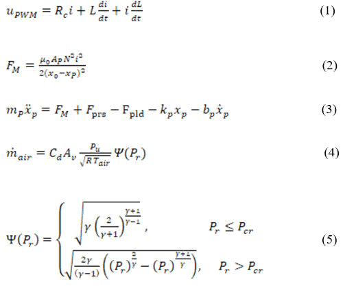
Rc : coil resistancee
L coil inductance (H)
N: number of turns in the coil
Ap : cross sectional area of the plunge (m2)
xp : plunge position (m)
x0 : minimum air gap between plunge and plunge seat (m)
mp : mass of the plunge (kg)
µ0 : permeability (H/m)
kp : spring constant of the plunge spring (N/m)
bp : friction coefficient between plunge and housing wall
Tair: air temperature
ratio of specific heat (= cp/cv)
Pcr: critical ratio of pressure (Pa)
Pr : fluid constant (0.528)
Fpre: pressure force (N)
Fpld: load force (N)
According to this, the AMESim model of the fast switching solenoid valve is obtained as shown in Figure 4.

Figure 4: AMESim model of the fast switching solenoid valve.
The aerodynamic model within the pneumatic cylinder space: The aerodynamic model within the air cylinder space shows the relationship between the pressure change in the cylinder space and the gas mass flow rate.
The filling and exhaust processes of the gas flowing in or out two spaces of the cylinder are the thermodynamic processes of the air mass,
The flow rate of the inflow and outflow space is equal to the rate of change of gas mass in space, according to the law of mass conservation for space A, where the mass flow rate entering the air cylinder space A and B is qa , qb , respectively, and the pressure in the two spaces is Pa , Pb .
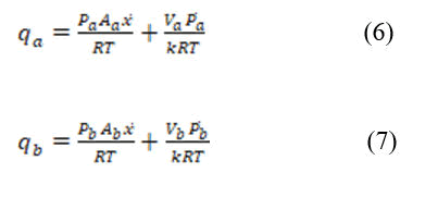
where R=287 J/(kgK)is the ideal gas constant, T=293K is absolute temperature and Va ,Vb is the volume of two spaces.
Model of the piston load system: According to the Newton's second law, the equation of motion of piston load system is given as below
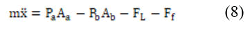
Where Pa and Pb is the pressure of A space and B space of cylinder, Aa and Ab is effective area of two spaces of cylinder, FL is load force, Ff is friction force, m is mass of piston rod and moving element.
According to the above mentioned mathematical model equations, AMESim simulation model of the electricpneumatic servo system with fast switching valves is given as Figure 5.

Figure 5: AMESim simulation model of the electric-pneumatic servo system with fast switching valves.
Fuzzy-PID Switching Control Method, AMESim and Matlab/Simulink Co-Simulation of the ElectroPneumatic Servo System with Fast Switching Valves
Fuzzy-PID switching control method
As can be seen from the mathematical model of the pneumatic servo positioning system using the fast switching solenoid valve, this control system is a nonlinear system, and therefore, the conventional PID control system cannot achieve an ideal control characteristic. Therefore, we use fuzzy PID switching control method to control system.
Regarding the control effects of PID control and fuzzy control methods, each has an advantage. Fuzzy control has good dynamic characteristics with little overshoot, but not high control accuracy, and oscillations occur near the target value.
By increasing the rank of the fuzzy controller and changing the number of input output variables, the accuracy of the fuzzy controller can be improved, but rule-making is very difficult. In terms of dynamic response characteristics, although PID controller is not good compared with fuzzy control, it has the advantages of good static performance and good controllability around the target point.
Its performance is determined by the PID parameters, which are not easily accessible and difficult to tune. At the beginning of the control process, the control performance of the fuzzy controller is better, which is faster in response and can prevent overshoot.
However, in the final stage of the control process, PID controller is more advantageous, which has a good static performance. Therefore, we designed the fuzzy-PID switching controller that it had two advantages.
If the error is relatively big, the controller selected the fuzzy control method so that achieve good dynamic performance and suppress overshoot. If the error is relatively small, the controller selected the PID control method so that improve the system performance, improve the control accuracy, and reduce the steady-state error.
Design idea of the fuzzy-PID switching controller: During the whole control process, the fuzzy PID switching controller combines the advantages of the two controllers according to the magnitude of the error and selects different controllers at different control stages to obtain better control effects. In the early stage of the control, when the absolute value e of the error obtained from the sampling of the system is greater than the error threshold e0 , the main consideration here is the dynamic nature of the system, and the fuzzy controller is chosen because the error value should be reduced as fast as possible. The fuzzy controller guarantees fast response of the system and can suppress the occurrence of overshoot phenomena.
When the response of the system is gradually stabilized and the absolute value e obtained from the sampling of the system is less than the error threshold e0, the static characteristics of the system must be taken into account, ensuring the control accuracy and decreasing the error, while preventing the generation of overshoot. The control method of the system should naturally be switched from fuzzy control to PID control.
Since the integration loop of PID controller is responsible for eliminating the error, it is possible to improve the performance of the system by effectively replacing the disadvantage that the fuzzy controller does not eliminate the steady-state error, and to improve the control accuracy. The control structure of this controller is shown in Figure 6.

Figure 6: Block diagram of the fuzzy-PID switching controller.
The aforementioned fuzzy PID switching controller has the advantages of both controllers. Fuzzy control has the advantage of fast response speed and suppressing overshoot, and PID controller has the advantage of high control accuracy, so the fuzzy PID switching controller, which offers both advantages, has good dynamics of the system.
However, this kind of conventional fuzzy PID switching control system also has the following disadvantages. The switching between the fuzzy controller and the PID controller automatically switches the computer according to the boundary value e0.
When the absolute value of the error e obtained by sampling the computer |e| is smaller than e0 , the system is controlled by PID controller to reduce the steady-state error. When the error |e|>e0 , the system switches to the fuzzy controller, the system switches to the fuzzy controller and decreases the error quickly. According to this, it can be seen that the choice of the boundary value e0 is the determinant that determines the performance of the switching controller.
If the boundary value e0 is too large, the advantage of the fuzzy controller cannot be fully demonstrated and overshoot can occur. If this value is too small, the steady-state error by fuzzy control is relatively large, so when the boundary value e0 is larger, it cannot be switched to the PID controller and the steady-state error elimination function of the PID cannot be exercised. Because of the inaccuracy of the control object, it is not possible to resolve the discrepancies with high-speed response, no-overshoot adjustment, and low steady-state error, depending only on the set-point set by experience. If the control of the system is to be stable, the stabilization of the control variable must be ensured and no significant changes must occur.
In other words, the switching of PID controllers and fuzzy controllers should not cause interference to the system so as to avoid overshoot. So, the output control of the two controllers at the switching point should not be the same or at least the different, which is indeed very difficult.
Thus, such a switching mode based on a fixed switching point cannot avoid affecting the stability of the system during the switching control of the control system, resulting in the prolongation of the tuning time or the generation of overshoot phenomena.
From the above analysis, the disadvantage of the fixed switching point-based fuzzy PID switching complex controller is that it does not allow smooth switching of both controllers. Therefore, in this paper, we use a fuzzy PID switching controller switched with fuzzy rules to realize two coherent smooth switching based on fuzzy rules. The schematic diagram of the fuzzy PID control system switching based on fuzzy rule is shown in Figure 7, where Ufuzzy is the output of the fuzzy controller and UPID is the output of the PID controller.
Detail design method of the fuzzy PID control system switching based on fuzzy rule: The PID controller and fuzzy controller are designed separately and applied to the position control system to perform simulation studies and obtain the optimal parameters of both controllers. Based on fuzzy rules, a switching module is designed.
The final test is carried out for the integrated fuzzy controller to obtain the optimal parameter solution for the system.

Figure 7: Schematic diagram of the fuzzy PID control system switching based on fuzzy rule.
Fuzzy switching module design: Based on the aforementioned disadvantages of fuzzy switching, we proposed fuzzy switching based on fuzzy rule switching. The preceding theory is that A or B, and the system instability occurs during the transition of the two controls.
To avoid the occurrence of such phenomena, in this paper, we select two complete actions, define the weights in two through the establishment of fuzzy rules, and determine the total output of the control variable through the average weights, where the fuzzy switching controller is T-S type. This allows the implementation of smooth switching while maintaining the advantages of both controls to avoid switching perturbations.
We define a fuzzy switching rule. If e is Ze and ec is Zec, then U is UPID else U is Ufuzzy. Among them, UPID is the output of PID control and UFuzzy is the output of fuzzy controller. Ze and Zec are linguistic variables of fuzzy switching rules and their membership functions are shown in Figure 8.

Figure 8: Membership functions of the fuzzy switching rule.
Among them, the magnitudes of a and b values represent the range of error and drift rates, and the various components of the two controllers can be obtained by varying values of a and b.
When the input error is e, its dependency degree is Ue, and the change rate of the input error is ec, the corresponding membership function is Uec, where, taking the "and" operations as a product, the output strength coefficients of the PID controller and the fuzzy controller are denoted by the following formula, respectively.
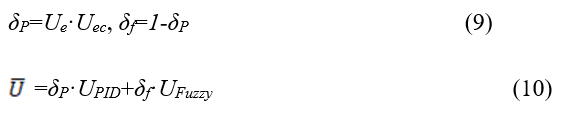
As can be seen from Equation 9 and 10, the output of the fuzzy PID switching controller uses the form of weighting factor and is not a single action. At the early stage of the system work, we can easily see that the larger the error e and the larger the error ec, the smaller the δP is based on the membership function. Therefore, the fuzzy controller mainly operates, and the system has a relatively fast response rate and the error quickly decreases.
Conversely, when the system enters the control stabilization step, the error e is small and the error variation rate is small, so that the membership function increases the δP and the main action is the PID controller, which ensures the control accuracy of the system and eliminates the steady-state error.
Therefore, a hybrid controller based on fuzzy switching rules has the advantages of both control and, at the same time, a stable transition is achieved to avoid switching perturbations of the system and ensure stable operation of the system.
Co-simulation Modeling of AMESim and Matlab/Simulink
In AMESim, the modeling of the Pneumatic part of the system is performed and the control section is modeled in Simulink, and parallel simulations are carried out, allowing the combination of two programs to use both AMESim's fluid mechanical simulation and MATLAB/Simulink's powerful numerical processing functions.
The AMESim and Matlab/Simulink co-simulation models of the pneumatic servo system using fast switching valves are shown in Figures 9 and 10.

Figure 9: AMESim model of the pneumatic servo system.

Figure 10: Matlab/Simulink model of the fuzzy-PID switching controller.
Result and Discussion
Using the parallel simulation model developed above, the control effect of the fuzzy PID switching controller is simulated to verify its control accuracy. The main parameters of the cylinder are set as follows: The piston diameter is 25 mm, the length of stroke is 0.3 m, the rod displacement is 0.06 m, the total mass being moved is 1 kg, the temperature at port 1 is 300K, and the pressure at port 1 is 8 bar.
The simulation results of the PID control, fuzzy control, and control characteristics of the fuzzy PID controller are shown in Figures 11-13. The step signal with amplitude 0.06 m is used as the input signal.

Figure 11: Simulation results of step response of PID control.

Figure 12: Simulation results of step response of fuzzy control.

Figure 13: Simulation results of step response of fuzzy PID switching control.
It can be seen from the simulation results that the conventional PID control has large overshoot and slow response time.
Fuzzy control has faster response than PID control, but it has larger static error.
In fuzzy PID control, the response of the system is fast, the tuning time is short, and the static error is small.
The time at which the system response reaches the actual position is 0.3 s and there is no overshoot.
The simulation study shows that the fuzzy PID switching control has strong robustness and good controllability for nonlinear systems such as pneumatic position servo system.
Conclusion
A new mathematical model is proposed to analyze the dynamic characteristics of the pneumatic servo positioning system using a high-speed shutter valve.
Based on the nonlinear model of the pneumatic servo positioning system using the quick-acting shutter valve, a new simulation model (AMESim model) is established. A new fuzzy PID control algorithm and a cylinder-based servo controller for the pneumatic servo-control system are developed. In order to validate the fuzzy PID control method proposed in this paper, a combination of Matlab/Simulink and AMESim is used to obtain the transient response of the pneumatic servohydraulic positioning system using a shutter valve. The maximum static error of the system is 0.2 mm and the response time is 0.3 s, which indicates that the fuzzy PID controller has a relatively high control precision.
References
- Mu S, Goto S, Shibata S, Yamamoto T (2019) Intelligent position control for pneumatic servo system based on predictive fuzzy control. Comput Electr Eng. 75:112–22.
[Crossref] [Google Scholar]
- Cai S, Wu S, Bao G (2013) Cylinder position servo control based on fuzzy PID. J Appl Math. 2013:1–10.
[Crossref] [Google Scholar]
- Noritsugu T (1986) Development of PWM mode electro pneumatic servomechanism Part I: Speed control of a pneumatic cylinder. J Fluid Power. 17(1):65–80.
[Google Scholar]
- Noritsugu T (1987) Development of PWM mode electro pneumatic servomechanism Part II: Position control of a pneumatic cylinder. J Fluid Power. 17(2):459–63.
[Google Scholar]
- Yang S, Wang S, Lin X (1993) On the frequency response characteristics of PWM high speed on-off valves. Proc 2nd JHPS Int Symp Fluid Power. 459-63.
[Google Scholar]
- Muto T, Yamada H (1990) Digital control of hydraulic actuator system operated by differential pulse width modulation. JSME Int J Ser III. 33(4):641–648.
[Google Scholar]
- Shibata S, Ben-Lamine MS, Toyohara K, Shimizu A (1999) Fuzzy control of vertical pneumatic servo systems using virtual reference. JSME Int J Ser C. 42(1):79–84.
[Google Scholar]
- Gao X, Feng ZJ (2005) Design study of an adaptive fuzzy-PD controller for pneumatic servo system. Control Eng Pract. 13:55–65.
[Crossref] [Google Scholar]
- Takosoglu JE, Dindorf RF, Laski PA (2009) Rapid prototyping of fuzzy controller pneumatic servo-system. Int J Adv Manuf Technol. 40:349–361.
[Crossref] [Google Scholar]
Citation: Ryu MS (2025) Research on Fuzzy-PID Switching Control of Electro-Pneumatic Servo System Based on Matlab-AMESim Co-Simulation. Br J Res. 12:132.
Copyright: © 2025 Ryu MS. This is an open-access article distributed under the terms of the Creative Commons Attribution License, which permits unrestricted use, distribution, and reproduction in any medium, provided the original author and source are credited.