Research Article - (2023) Volume 5, Issue 3
Received: 31-Aug-2023, Manuscript No. jbtc-23-17600; Editor assigned: 05-Sep-2023, Pre QC No. jbtc-23-17600 (PQ); Reviewed: 19-Sep-2023, QC No. jbtc-23-17600; Revised: 26-Sep-2023, Manuscript No. jbtc-23-17600 (R); Published: 24-Oct-2023, DOI: 10.35841/jbtc.23.5.21
Light Emitting Diodes (LEDs) play an essential role in lighting and green earth activities because of their high efficiency, longevity and reduction of carbon dioxide emissions in illumination. However, the brightness level of LED light sources must be adjusted appropriately for backlight source or illumination, so Pulse Amplitude Modulation (PWM) is a commonly used method of LED control. This paper experimentally investigated the human visual comfort effect of the light effect obtained using different PWM frequencies on an object in a sensor-based intelligent lighting system. The histograms of the object were created according to the light frequency and the results were discussed.
LED; Pulse Width Modulation (PWM); Color image; Histogram specification; Flicker effect; Kruithof curve
Energy saving and efficiency, using green energy resources and low carbon emissions are essential issues worldwide. Lighting is vital to worldwide energy consumption in many aspects. Regarding energy consumption, lighting constitutes a significant portion of the electrical energy produced in developing countries. More than 20% of the energy provided in developed countries is consumed by lighting. Fluorescent lamps and incandescent filament lamps have been used in lighting devices and these lamps are replaced by LEDs due to their long life, high luminous efficiency and high performance [1].
LED light sources are used in driver circuits and these drivers can cause visible flicker. Flicker is defined as the change in the intensity of a light source due to fluctuations in the light source, power circuit flicker or incompatibility with an external dimmer. As shown in Figure 1, the flicker can be measured with two different parameters: Percent flicker and flicker index: Percentage flicker can be defined as the ratio between the maximum and minimum light in a cycle. On the other hand, the flicker index requires accurate measurement of the waveform shape with complex integral mathematics. For this reason, the expression per the cent flicker is used more than the flicker index to qualify the amount of flicker. Additionally, the IEEE PAR1789 standard specifies possible health risks for higher percentages of flicker (Figure 1).
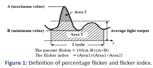
Figure 1: Definition of percentage flicker and flicker index.
The human eye's time-varying excitations cannon be distinguished in cases where light excitations change very slowly, as in natural lighting and in cases where light excitations change very quickly, as in discharge lamps working with alternating current. If the brightness of a light source changes periodically and this change appears to the eye as a steady glowing light source, this flicker frequency is critical. The mean value of the periodically changing luminance (Lmean) is calculated by equation (1), where L is the instantaneous value of the periodically changing luminance and T is the period of the periodically changing luminosity [2].

The Kruithof curve defines a region of lighting levels and color temperatures generally seen as comfortable or pleasant to an observer. This empirical curve captures the "comfortable" lighting range parameterized by brightness and color temperature, called the Kruithof curve. It has been empirically determined that the Kruithof curve for a given value of L luminance and color temperature (K) is comfortable for humans; this curve is seen in Figure 2.
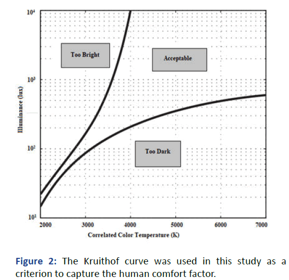
Figure 2: The Kruithof curve was used in this study as a criterion to capture the human comfort factor.
PWM is a type of modulation that adjusts brightness by quickly turning the light source on and off. Frequency and duty cycle are essential parameters in PWM. The period equals the sum of the TON time and the TOFF time. The Frequency (F) of a PWM signal is found in 1/period. The PWM signal is shown in Figure 3 and the duty cycle expression is given in equation [3].
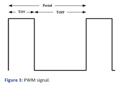
Figure 3: PWM signal.

Image processing is a method used to obtain a specific image by converting the image into a digital form or to obtain the desired result from the image with software. Today, image processing is used in many fields, such as medicines, military, security, facial recognition, emotion analysis, robotics and classification. Histograms allow us to see the frequency distribution of a data set as, a graphical representation of the image gray value distribution. For example, as you move to the left on the X-axis (closer to the origin), pixels of darker and black areas are obtained [4].
In this paper, the visual comfort effect of the light effect on a vase object was experimentally investigated using different PWM frequencies in an intelligent lighting system using a phototransistor sensor. The reference illuminance the environment was adjusted to 300 lux using a potentiometer and LED panels were used to obtain the required illuminance level. According to the light frequency, the histograms of the object were created in the MATLAB software environment and interpreted.
Experimental Setup
The power of the LED panel used was 36 watts, the maximum luminous flux value is 3204 lumens, the color temperature is 6500 K and the luminous factor was 89 lm/W. An LED panel with a Color Rendering Index (CRI) >80 is used. The light distribution curve of the LED panel used is given in Figure 4. Based on the EN 12464 lighting of indoor workplaces standard, the recommended classroom light level is 300 lux. The color temperature of the LED panel was kept at 6500 K and the illumination the environment was 300 lux [5]. Considering these values, the Kruithof curve in Figure 4 shows that the light values are acceptable and in the comfort zone.
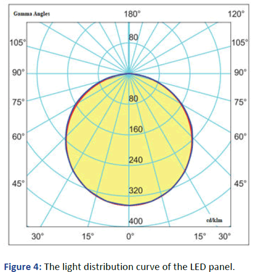
Figure 4: The light distribution curve of the LED panel.
A TEMT6000 phototransistor light lensor was used in this study [6]. This sensor can measure illuminance up to 1000 lux with a peak sensitivity of approximately 580 nm, with a spectral sensitivity curve adapted to suit human eye sensitivity. The photosensor generates analog current information from a variable 0-5 V voltage read through a 10 K resistor. The current change of the sensor with the brightness is shown in Figure 5.
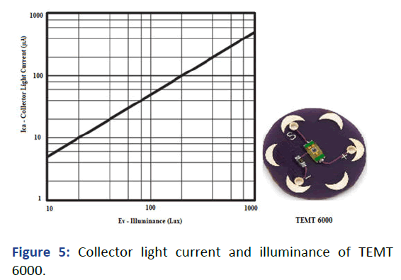
Figure 5: Collector light current and illuminance of TEMT 6000.
The TEMT6000 sensor has angle accuracy of φ=± 60°. The relative radiation sensitivity and angular displacement are given in Figure 6. This photosensor is strictly linear between ≤ 10 lux and ≥ 1000 lux and its typical photocurrent is specified for 50 μA (at 100 lx). The photocurrent (IPCE) illumination equation of TEMT6000 is given below [7].

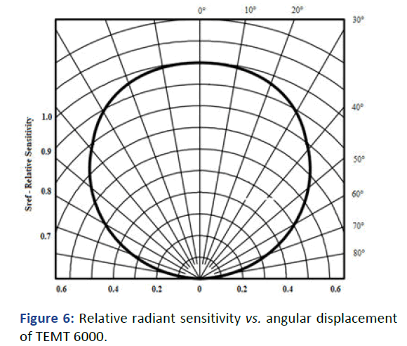
Figure 6: Relative radiant sensitivity vs. angular displacement of TEMT 6000.
The ambient reference value can be adjusted with a 10 K potentiometer connected to the TEMT6000 ambient light sensor. The reference value was set at 300 lux. The light is increased if the analog information received from the phototransistor light sensor is below the reference limit. Figure 7 shows the reference signal generation according to ambient light [8].
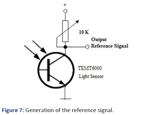
Figure 7: Generation of the reference signal.
In the smart LED lighting system, the ambient reference value can be obtained and connected to the TEMT6000 ambient light sensor so that the potentiometer adjusts the block graph shown in Figure 8. The reference value was set to 300 lux. If the light information received from the ambient sensor is lower than the reference lux limit, the amount of light is increased.
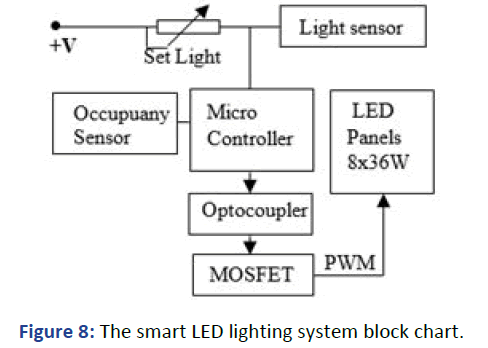
Figure 8: The smart LED lighting system block chart.
Increasing or decreasing the ambient light is accomplished with the PWM signal generated by the algorithm seen in Figure 9. The PWM signal produced by the control card determines the light level the LED panels pass through the MOSFET transistor [9].
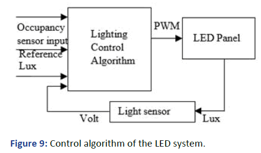
Figure 9: Control algorithm of the LED system.
In the experimental setup, a colored the flower vase was used as the object. The distance between the flower vase and the ceiling was 1.1 meters. The ceiling and walls are light to color. The image of the experimental environment is given in Figure 10.
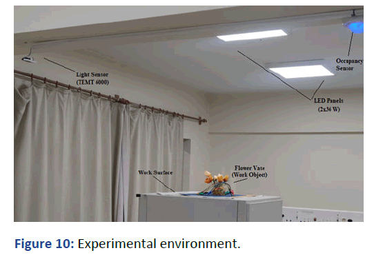
Figure 10: Experimental environment.
Experimental measurements were made under light frequencies of 25 Hz, 50 Hz, 125 Hz, 166 Hz and 250 Hz. 5 images were taken between 0. Second and fourth seconds at each PWM light frequency. All images were obtained from the camera recording with a resolution value of 720. The average pixel value of each picture is shown with a red line and is given as numerical values in the figure tag. In histograms, the y-axis indicates the number of pixels and the x-axis shows the brightness value between 0 and 255 obtained using 8 bits. The histograms show how illuminated each pixel is. The left side of the X-axis represents pure black and the right means brightness with pure white. The number of pixels of the relevant brightness value on the Y-axis is shown numerically.
In the video recording taken at 25 Hz light frequency, the histogram pixel values of the image vary considerably according to time. In Figure 11, the red line shows the average of the pixels in the image histogram. The origin point on the xaxis shows the dark level. As it moves from the origin point to the left of the x-axis, the image brightness in light color increases [10].
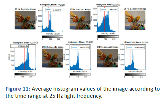
Figure 11: Average histogram values of the image according to the time range at 25 Hz light frequency.
While the pixel average of the images taken at 25 Hz between 0 and 1 second is 77.2523, the standard in the second is 122.1436. When watching the video recording of the pictures, the flicker effect caused by the pixel changes according to time disrupted the visual comfort. The average of the five values here is 88.6269.
In the video recording taken at 50 Hz light frequency, the histogram pixel values of the image vary considerably according to time. Figure 12 shows the average pixel values of the pictures taken from the image recorded between 0 and 4 seconds [11]. For example, while the average pixel value of the image between 0 and 1 is 94.0241, the average pixel value at the 3rd second is 165.9061.
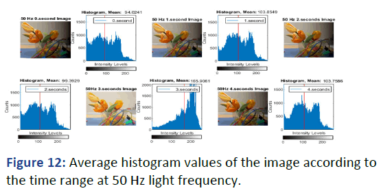
Figure 12: Average histogram values of the image according to the time range at 50 Hz light frequency.
When viewing a video recording of images at 50 Hz, the flicker effect caused by the pixel changes according to time disrupted the visual comfort. The average of the five values here is 113.387.
In the video recording taken at 125 Hz light frequency, the histogram pixel values of the image vary considerably according to time. Figure 13 shows the average pixel values of the pictures taken from the image recorded between 0 second and 4 seconds. For example, while the average pixel value of the image between 0 and the 1st second is 72.3844, the average pixel value in the 1st second is 152.4702.
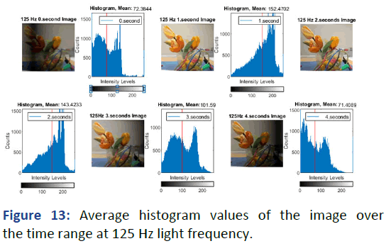
Figure 13: Average histogram values of the image over the time range at 125 Hz light frequency.
The flicker effect caused by the pixel changes according to the time when watching the video recording of the images at 125 Hz disrupted the visual comfort. The average of the five values here is 108.255.
The histogram pixel values of the image in the video recording taken at light frequency of 166 Hz almost do not change with time [12]. Therefore, these values can be considered constant when the video recording is watched or compared to the picture. Figure 14 shows the average pixel values of the photographs taken from the image recorded between 0 seconds and fourth seconds. The average pixel value of the image is between 0. The second and first second is 120.838, while the average pixel value at the second is 121.1245

Figure 14: The average histogram values of the image over the time range at a light frequency of 166 Hz.
When the video recording of the images was watched at 166 Hz, the flicker/frequency effect caused by the time change of the pixels could not be noticed and it was observed that visual comfort was created. The average of five values here is 120.6596.
In the video recording shot at 250 Hz light frequency, the histogram pixel values of the image almost do not change over time. Therefore, these values can be considered constant when watching the video recording or examining the pictures. Figure 15 shows the average pixel values of the images taken from the image recorded between 0 second and 4 seconds. For example, the average pixel value of the image between the 0th and the 1st seconds is 120.5175, while the average pixel value at the 1st second is 121.8949.
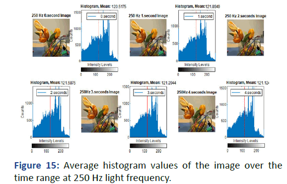
Figure 15: Average histogram values of the image over the time range at 250 Hz light frequency.
When watching the video recording of the images at 250 Hz, the flicker effect caused by the pixel changes according to time was not observed and visual comfort was provided. The average of five values here is 121.2657.
When the standard deviation values of the frequencies were examined according to Table 1, significant standard deviation (std) values were obtained at 25 Hz, 50 Hz and 125 Hz light frequencies and minimal std values at 166 Hz and 250 Hz (Table 1).
| Time | 25 Hz | 50 Hz | 125 Hz | 166 Hz | 250Hz |
|---|---|---|---|---|---|
| 0 second | 77.2523 | 94.0241 | 72.3844 | 120.838 | 120.5175 |
| 1 second | 92.0103 | 103.8549 | 152.4702 | 119.9058 | 121.8949 |
| 2 seconds | 122.1436 | 99.3929 | 143.4233 | 121.1245 | 121.5875 |
| 3 seconds | 76.4195 | 165.9061 | 101.59 | 120.3055 | 121.2044 |
| 4 seconds | 75.3061 | 103.7586 | 71.4089 | 121.1243 | 121.1243 |
| Mean | 88.62636 | 113.3873 | 108.2554 | 120.6596 | 121.2657 |
| Std | 19.94155 | 29.63351 | 38.34237 | 0.537937 | 0.520337 |
Table 1: Average and standard deviation (std) values of light frequencies over a time range.
In Table 1, whether there is a flicker according to time in the vase object image in the camera kept fixed under a specific light frequency has been observed. The visual comfort status of these vibrations was determined from the average pixel values of the images taken at particular seconds. The average pixel value of the image remained constant over time or the low standard deviation value was used to measure image quality. In Figure 16, the average and STD changes of the light frequencies are seen [13]. At 166 and 250 Hz, the std values are pretty low and the pixel density is relatively high.
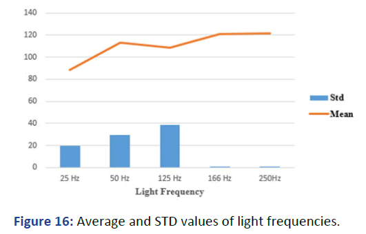
Figure 16: Average and STD values of light frequencies.
The Color Rendering Index (CRI) and color temperature (kelvin) are essential for visual comfort. The scale range of the color-rendering index is 0-100. Natural light has a CRI of 100 and a CRI greater than 80 is recommended. The colorrendering index of the LED lamps chosen for illuminating the space is greater than 80 and the color temperature is greater than 80. The color temperature of the LED panel used was 6500 K. The region where the 300-lux reference value provided by intelligent lighting, according to the Kruithof curve and the color temperature of the LED lamp intersect, is located in the visual comfort zone.
In this study, color temperature and lux brightness values are discussed in terms of human visual comfort and fluctuations. The high flicker effect in images taken from 25 Hz, 50 Hz and 125 Hz light frequencies according to time has been shown with high standard deviations and it has been seen that these frequencies do not provide visual comfort. On the other hand, the standard deviations of the images taken at 166 Hz and 250 Hz light frequencies are low and no flicker effect is observed in the pictures. Therefore, the evaluation of the human vision comfort factor concluded that it would be healthier to adjust the light PWM frequency to around 160 Hz or above these frequency values.
The data used to support the findings of this study are available from the corresponding author upon request.
The author declares that there are no conflicts of interest regarding the publication of this paper.
Citation: Ozcelik MA (2023) Investigation of the Effect of Light PWM Frequency on the Object in Terms of Human Visual Comfort. BioEng BioElectron. 5:21.
Copyright: © 2023 Ozcelik MA. This is an open-access article distributed under the terms of the Creative Commons Attribution License, which permits unrestricted use, distribution, reproduction in any medium, provided the original author and source are credited.