Review Article - (2025) Volume 16, Issue 1
Received: 22-Aug-2023, Manuscript No. AASRFC-23-17433; Editor assigned: 24-Aug-2023, Pre QC No. AASRFC-23-17433 (PQ); Reviewed: 07-Sep-2023, QC No. AASRFC-23-17433; Revised: 14-Jan-2025, Manuscript No. AASRFC-23-17433 (R); Published: 21-Jan-2025, DOI: 10.36648/0976-8610.16.1.56
The security of a home largely depends on the effectiveness of its door lock system. However, instances of occupants forgetting to lock the door or doubting its status due to time constraints are not uncommon. To address this issue, we propose an innovative android-based application called the door security system, which leverages Internet of Things (IoT) technology to monitor, control, and enhance the security of a house. The system utilizes the MQTT cloud as a communication protocol between the smartphone and the door lock mechanism. The door security system incorporates various sensors to ensure comprehensive monitoring. A Passive Infrared (PIR) sensor is implemented within the door lock to detect any movement near the door, while a touch sensor is installed on the door handle to recognize human interaction. In the event of forced entry, an alarm will promptly ring and send notifications to the house occupants, effectively alerting them about the presence of an intruder. Evaluation results demonstrate the accuracy of the motion detection sensor, accurately detecting movements up to 1.6 meters ahead. Additionally, the communication between the smartphone and the door lock system is securely encrypted, ensuring the safe transmission of messages. Furthermore, the system incorporates Simple Mail Transfer Protocol (SMTP) to send an email notification to the occupants, including an attachment-a photo captured using the ESP32-CAM. The proposed door security system, with its integration of IoT technology, presents a robust solution to augment home security. By providing real-time monitoring, remote control, and immediate notifications, it offers peace of mind to house occupants, allowing them to securely manage their doors from anywhere. The utilization of sensors, MQTT cloud, and encrypted communication ensures the system's reliability and effectiveness.
Door security system; Internet of things; Sensors; NodeMCU
The security of a house heavily relies on the integrity of its doors. An easily accessible door poses a significant threat, enabling potential thieves to enter and steal valuable possessions. Traditional doors initially relied on physical keys for locking and unlocking, but with technological advancements, digital doors were introduced, offering keyless entry options. However, digital doors are also susceptible to break-ins or damage, which may go unnoticed until the homeowner returns.
To ensure consistent home security, occupants typically strive to lock the door whenever they leave or rest inside the house. Unfortunately, instances of forgetting to lock the door due to time constraints or uncertainty about its status are not uncommon, posing a significant threat to home security [1]. This paper proposes the integration of Internet of Things (IoT) technology to address these challenges.
IoT refers to a network structure where objects and individuals possess unique identities and the ability to transmit data over a network without necessitating humanto- human or human-to-computer interactions. Leveraging IoT, this research aims to enhance the security of home doors by developing a system that can remotely monitor the door's status, control its locking mechanism via a smartphone, and implement encrypted MQTT cloud communication for secure data transfer.
The system employs various sensors such as Passive Infrared sensors (PIR) to detect movement, magnetic sensors to determine whether the door is open or closed, and touch sensors to detect physical contact. Additionally, microcontrollers are utilized to control connected devices, MOSFETs function as automatic switches, digital door locks offer keyless access, alarms provide intrusion alerts, and LED lights enable remote illumination control.
The MQTT protocol, widely used in IoT network communication, facilitates a publish/subscribe mechanism. By subscribing to specific topics, a receiver device establishes a connection with the server, ensuring that any generated messages related to the subscribed topics are transmitted to the receiver. In contrast, traditional HTTP requires periodic client requests to the server for message retrieval. The proposed system leverages MQTT cloud communication to securely improve house security.
This research focuses on enhancing the security of home doors through the implementation of IoT technology, allowing remote monitoring, control, and encrypted communication via MQTT cloud. In the event of forced entry, the door will activate an alarm and send notifications to the occupants' smartphones through the MQTT cloud.
The structure of this paper consists of four sections. Section 1 provides an introduction to the research. Section 2 explores previous work conducted in this field. Section 3 presents the system design approach in detail [2]. Finally, section 4 concludes the research findings.
In summary, this research aims to enhance home security by leveraging IoT technology to monitor and control the status of house doors, enabling remote access through encrypted MQTT cloud communication. Additionally, the system incorporates alarm functionalities and smartphone notifications to alert occupants in the event of a forced entry.
The application of Internet of Things (IoT) in smart home technology has been widely explored in previous research, focusing on remote control and monitoring of various appliances such as fire, gas, water, air conditioners, and fans [3]. Additionally, some studies have emphasized energy efficiency to reduce consumption [4]. Within the realm of home security systems, researchers have investigated various approaches. Agarwal et al. introduced the HDSL system, a home security solution that addresses concerns related to laziness [5]. The HDSL system offers two main functions: "home security," which analyses individuals outside the door, and "smart locking," which enables house members to control the locking system via their mobile devices. The system incorporates a Raspberry Pi 3 for hardware control, including cameras, motion sensors, and electric locks.
The research methodology involves controlling the locking system using bluetooth and receiving messages from the internet. The system initiates by checking for a bluetooth handshake. Upon successful handshake, the door unlocks, and after a specified duration, it automatically locks again. In the absence of a bluetooth handshake, the system checks for incoming messages. Upon receiving an "unlock door" message, the system unlocks the door and locks it upon receiving a "lock door" message. In the absence of any messages, the system examines the possibility of a visitor. If a signal from the doorbell is detected, the system captures photos using the camera and sends them to the user's email. In the absence of a doorbell signal but with motion detected by the sensor, the system assumes the presence of an intruder. It captures photos, sends them as a warning to the user's email, and issues a warning message via the internet.
Security concerns have become increasingly significant worldwide, and this research aims to provide a comprehensive literature review on door locks and gate security systems necessary for home, industrial, and vehicle security, where the risk of intrusion continues to rise. Previous studies have explored various security systems, including traditional alarm-based systems. Recent advancements have led to the development of microcontroller-based systems, utilizing technologies such as GSM, GPS, and multiple sensors. Software tools like MATLAB and Proteus, as well as biometric measures such as face recognition, iris scanning, RFID, smart cards, and passwords, have also been incorporated. Each system has its own advantages and disadvantages.
Most systems employ SMS communication for costeffectiveness, reliability, and quick message delivery. As security concerns escalate, security monitoring systems need to leverage the latest technologies.
Researchers have presented door lock security monitoring systems based on embedded systems and Zigbee, while others have implemented automatic password protection to prevent hacking. Enhanced security systems have been developed based on the Android platform, wireless techniques, and embedded systems. The door lock security landscape has undergone significant modifications in recent years, with further changes anticipated in the future.
A study by Nareshkumar, Kamat, and Shinde describes a system that allows door control through a mobile device operated by a smartphone [6]. This system incorporates a camera, Raspberry Pi model B3 with built-in WiFi/GSM module, a PIR sensor, a biometric system, and a mobile device. When an individual stands in front of the door, the camera detects their presence and sends the image to the user's mobile device. Users can control the door through their smartphones, with the mobile app providing specifications for device control. The system utilizes IoT (Internet of Things) to transmit the captured image from the web camera to the user's mobile device via Raspberry Pi [7].
In the presence of guests, they can activate the doorbell switch, triggering the speaker to prompt them to stand in front of the camera for a photograph. The system then sends the photo to the primary host's email address, and if necessary, to the secondary host as well, with the subject line "someone at the door." If the primary host wishes to open the door, they can reply to the email with the subject line "allow person." If the primary host chooses not to open the door, they can reply to the email without modifying the contents. The primary host has a time limit to respond [8]. In the absence of a reply, the system sends the guest's photo to the secondary host and informs the guest that the primary host has not responded. The secondary host also has a time limit to make a decision. If the secondary host does not respond, the system notifies the guest of the lack of a reply.
Kodali et al. proposed a home security system that utilizes a PIR motion sensor to detect intruders. When motion is detected, the system triggers a voice call to the homeowner, who then needs to determine if it is an intruder or not. However, the research by Kodali in 2016 did not specify how the prototype helps the owner differentiate between an intruder and a guest, although the use of a camera is mentioned for further research [9].
Based on the reviewed literature, there are only a few researchers who have discussed IoT, home security systems, and remote door control. Therefore, this research aims to develop a system that can remotely monitor and control doors, receive alerts when movement is detected near the door, grant access to trusted individuals, provide a log of door activity including who opened or closed the door and when, and send notifications if the door remains open beyond a certain time limit [10]. The main differences between this proposed system and existing works lie in the program's ability to grant access to other users and the homeowner's ability to view the log history of door activity.
Requirements
Software Requirements
Remote database (PhpMyAdmin): The software requirement for the remote database in this research project is PhpMyAdmin. PhpMyAdmin is a web application that offers a user-friendly Graphical User Interface (GUI) for managing the MySQL database management system. It allows users to interact with the database, perform various operations, and manage database objects easily. PhpMyAdmin is widely recognized as the most popular administration tool for MySQL [11]. It has gained popularity due to its convenience, extensive features, and user-friendly interface. The tool is used by millions of users worldwide and has received numerous awards and honors for its contribution to the field of database management.
In this research project, PhpMyAdmin will be utilized as the primary tool for managing the remote database. It will provide the necessary functionalities to create and manage database tables, execute queries, import and export data, and perform other administrative tasks related to the database [12]. The intuitive GUI of PhpMyAdmin will enable researchers and system administrators to interact with the database efficiently and effectively. By utilizing PhpMyAdmin, the research project will benefit from its robust features, ease of use, and widespread acceptance in the database management community. Researchers will be able to manipulate and analyze the data stored in the remote database seamlessly, supporting the objectives of the research project [13].
Arduino IDE (Integrated Development Environment): The software requirement for this research project includes the use of the open-source Arduino IDE (Integrated Development Environment) (Figure 1).

Figure 1: Arduino IDE.
Arduino IDE is a software platform that provides a convenient and user-friendly environment for writing, compiling, and uploading code to Arduino microcontroller boards. Arduino IDE is widely used in the field of electronics and embedded systems development. It supports a variety of Arduino boards and provides a simplified programming language based on Wiring, making it accessible even to beginners. The opensource nature of Arduino IDE allows for community contributions and continuous improvement of the software.
With Arduino IDE, researchers can write code in a high-level language, which is then compiled and uploaded to the Arduino board. The IDE offers features such as syntax highlighting, code suggestions, and a serial monitor for debugging and interacting with the board. It also provides a library manager, allowing users to easily add additional functionality to their projects through third-party libraries. By using Arduino IDE, researchers can develop and upload firmware to the Arduino-based hardware components used in the research project. This includes programming the NodeMCU, ESP-32 Cam, and other Arduino-compatible devices. The IDE simplifies the development process, making it easier to write and test code for controlling sensors, actuators, and other components connected to the Arduino boards.
Overall, Arduino IDE serves as an essential tool for the software development aspect of the research project, enabling researchers to program and control the Arduinobased hardware components effectively.
Hardware requirements
The hardware requirements for this research project are as follows:
NodeMCU: NodeMCU is an open-source IoT platform based on the ESP8266 Wi-Fi module. It provides built-in Wi-Fi connectivity and acts as a gateway for sending data to web services. NodeMCU will be used to connect various sensors and components to the internet and send data to the web service (Figure 2 and Table 1).
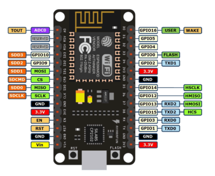
Figure 2: NodeMCU.
| Pin Category | Name | Description |
|---|---|---|
| Power | Micro-USB, 3.3 V, GND, Vin | Micro-USB: NodeMCU can be powered through the USB port. 3.3 V: Regulated 3.3 V can be supplied to this pin to power the board. GND: Ground pins. Vin: External power supply. |
| Control Pins | EN, RST | The pin and the button reset the microcontroller. |
| Analog Pin | A0 | Used to measure analog voltage in the range of 0-3.3 V. |
| GPIO Pins | GPIO1 to GPIO10 | NodeMCU has 10 general purpose input-output pins on its board. |
| SPI Pins | SD1, CMD, SD0, CLK | NodeMCU has four pins. |
| UART Pins | TXD0, RXD0, TXD2, RXD2 | NodeMCU has two UART interfaces, UART0 (RXD0 and TXD0) and UART1 (RXD1 and TXD1). UART1 is used to upload the firmware/program. |
| I2C Pins | NodeMCU has I2C functionality support but due to the internal functionality pins we find which pin is I2C. |
Table 1: NodeMCU pin description.
ESP-32 cam: ESP-32 cam is a low-cost development board with a built-in camera module. It allows capturing images and video, making it suitable for tasks such as surveillance or image processing (Figure 3).
The ESP-32 Cam will be used to capture images of individuals in front of the door and send them to the user's mobile device.
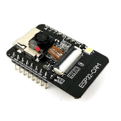
Figure 3: ESP-32 cam.
FDI programmer: The FDI (Future Technology Devices International) programmer is a device used for converting RS-232 or TTL serial transmissions to and from USB signals (Figure 4). It is commonly used for programming and communication with Arduino boards. The FDI programmer will be used to program and communicate with the Arduino boards used in the research project.
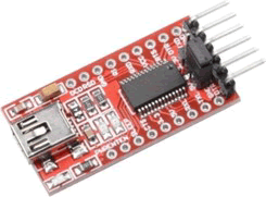
Figure 4: FDI programmer.
PIR sensor: PIR (Passive Infrared) sensor is an electronic sensor that detects motion by sensing changes in infrared radiation. It will be used to detect movement near the door and trigger actions such as capturing images or sending alerts (Figure 5).
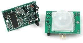
Figure 5: PIR (Passive Infrared).
Alarm buzzer: The alarm buzzer is an audio device that produces a sound signal when a voltage is applied to it. It will be used to provide audible alerts or warnings when certain events occur, such as detecting an intruder (Figure 6).

Figure 6: Alarm buzzer.
LED lights: LED (Light-Emitting Diode) lights are semiconductor light sources that emit light when current flows through them. They will be used for visual indications or status feedback, such as indicating if the door is locked or unlocked (Figure 7).

Figure 7: LED (Light-Emitting Diode) lights.
Solenoid lock: The solenoid lock is an electrical locking mechanism that can be controlled by applying or removing power. It will be used to lock or unlock the door remotely based on user commands (Figure 8).

Figure 8: Solenoid lock.
Batteries (9 V): Batteries are portable power sources that provide electrical energy. 9 V batteries will be used to power the components and ensure their operation even during power outages or when the main power source is unavailable (Figure 9).

Figure 9: Batteries.
Jumper wires: Jumper wires are used to establish connections between different components on a breadboard or circuit. They will be used to connect the various sensors, actuators, and Arduino boards together in the research project (Figure 10).

Figure 10: Jumper wires.
These hardware components are essential for implementing the remote door monitoring and control system described in the research project. They enable the sensing of movement, capturing of images, remote access control, and the overall functioning of the system.
Implementation
Problem statement: Sometimes, house occupants forget to lock the door due to hurry when leaving the house or may doubt whether they have locked the door or not. This poses a threat to home security.
To address this problem, an implementation plan can be developed to create a remote door monitoring and control system. The system will allow users to monitor the status of the door remotely and provide control over locking and unlocking the door. By implementing this system, users can have peace of mind knowing that they can check and control the door's status even when they are away from home.
To address the problem statement, the implementation of the remote door monitoring and control system can involve the following steps:
Setting up the NodeMCU and ESP-32 cam:
• Connect the NodeMCU and ESP-32 cam to the computer using jumper wires.
• Install the necessary drivers and libraries for NodeMCU and ESP-32 cam.
• Configure the Wi-Fi settings on the NodeMCU to establish an internet connection.
Configuring the remote database:
• Install and set up a web server with PHP and MySQL support.
• Set up a remote database using phpMyAdmin, which provides a convenient GUI for managing the MySQL database.
• Create a database schema to store the necessary information, such as user access logs and door status.
Writing the Arduino code:
• Open the Arduino IDE and create a new sketch.
• Write the code to initialize the sensors and actuators, such as the PIR sensor, buzzer, LED lights, and solenoid lock.
• Implement the logic to capture images using the ESP-32 Cam and send them to the user's mobile device.
• Write code to establish communication with the remote database and store/access data, such as door access logs and user permissions.
Uploading the code to NodeMCU:
• Connect the NodeMCU to the computer using the FDI programmer.
• Compile the Arduino code and upload it to the NodeMCU using the Arduino IDE.
• Ensure that the code is successfully uploaded and running on the NodeMCU.
Testing and integration:
• Place the PIR sensor near the door to detect movement.
• Test the system by simulating different scenarios, such as someone approaching the door, unauthorized access attempts, and remote door control using a mobile device.
• Verify that the system captures images, sends alerts, and performs the desired actions based on the detected events.
• Integrate the different components and verify their proper functioning together.
User interface development:
• Develop a user interface, such as a mobile application or web interface, to allow users to monitor and control the door remotely.
• Implement features like viewing door access history logs, granting access to trusted individuals, and receiving notifications for door status.
Deployment and evaluation:
• Install the system on the target location, such as a home or office.
• Conduct a thorough evaluation to ensure the system's reliability, security, and usability.
• Collect feedback from users and make any necessary improvements or enhancements based on their suggestions.
By following these implementation steps, the remote door monitoring and control system can be developed and deployed to address the problem statement of ensuring home security by allowing remote monitoring and control of the door.
Workflow
Initialization
• Start the remote door monitoring and control system.
• Connect the NodeMCU and ESP-32 Cam to the power source.
• Ensure that the necessary software is running on the NodeMCU.
Monitoring door status
• Activate the PIR sensor to detect any motion near the door.
• If motion is detected, capture an image using the ESP-32 cam.
• Send the captured image to the user's mobile device or email address for notification.
User interaction
• Allow the user to remotely access the system through a smartphone or web interface.
• Provide options to view the current status of the door (locked/unlocked) and the recent activity log.
Remote door control
• Enable the user to remotely lock or unlock the door using the smartphone or web interface.
• Implement a secure authentication mechanism to ensure authorized access.
Alarm and notification
• Integrate an alarm buzzer to sound an alert when unauthorized access is detected or if the door is left unlocked for an extended period.
• Send real-time notifications to the user's mobile device or email address regarding any suspicious activity.
Backup power
• Ensure that the system is equipped with batteries or a backup power source to maintain functionality during power outages.
Error handling
• Implement error handling mechanisms to address any unforeseen issues or system failures.
• Provide appropriate error messages or notifications to the user in case of system malfunction.
Logging and reporting
• Maintain a log of door activity, including timestamps and user interactions.
• Enable the user to access the door activity log for monitoring and security purposes.
Testing and maintenance
• Perform thorough testing of the system to ensure its reliability and accuracy.
• Regularly update and maintain the system software to address any vulnerabilities or bugs.
System enhancement
• Continuously seek feedback from users and consider implementing additional features or improvements based on their needs and suggestions (Figure 11).
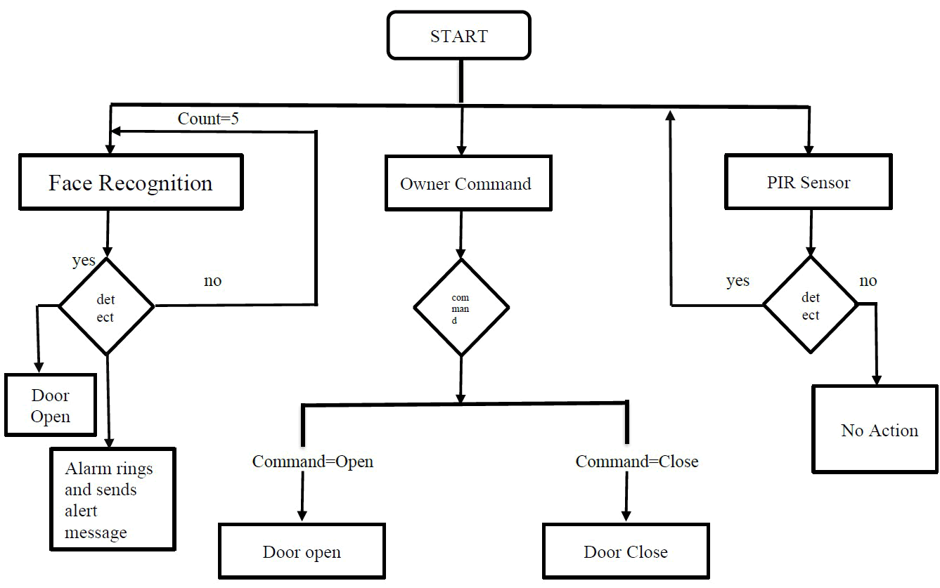
Figure 11: Workflow.
Circuit Diagram
In the circuit diagrams, the main components used are the PIR sensor, alarm buzzer, NodeMCU microcontroller, ESP-32 Cam, solenoid lock, and FDTI Programmer.
The PIR sensor is placed in front of the door to detect motion (Figure 12). It has three pins: GND, VCC, and digital OUT. These pins are connected to the corresponding pins on the NodeMCU microcontroller (GND, Vin, and D1).
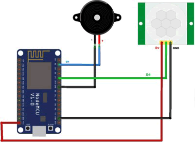
Figure 12: Circuit diagram for motion detection.
When motion is detected by the PIR sensor, it sends a signal to the NodeMCU microcontroller. The microcontroller then activates the alarm buzzer, producing an audible alert. Additionally, the microcontroller sends an alert message to a specified email address, notifying the owner that someone is trying to open the door.
The ESP-32 cam is connected to the solenoid lock and the FDTI programmer. The solenoid lock is powered by a 12 V power supply. The ESP-32 Cam is used for face recognition to open the door. When the alarm buzzer rings, indicating an attempted intrusion, the system can take a photograph of the person in front of the door using the ESP-32 cam (Figure 13). The photo is then sent to the owner's email address for further identification and monitoring.
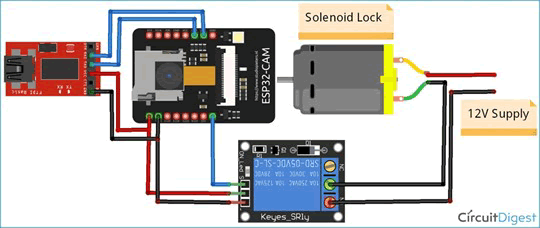
Figure 13: Circuit diagram for face recognition
Overall, the circuit diagram illustrates the integration of various components to create an IoT-based door security system, which combines motion detection, alarm triggering, face recognition, and email alerts to enhance home security.
These are outputs for the door status open (Figure 14).

Figure 14: Status of the door in the mobile view when it is given open command.
Here we can get data 1 when door was open (Figure 15).

Figure 15: Get Data of the door status in the mobile view when it is given open command.
Here the light become on because the owner allowed opening the door, so now the door is in open state (Figure 16).
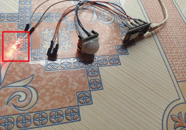
Figure 16: Status of the door that indicates it is in open state.
These are outputs for the door status open (Figure 17).

Figure 17: Status of the door in the mobile view when it is given close command.
Here we can get data 0 when door was open (Figure 18).

Figure 18: Get data of the door status in the mobile view when it is given close command
Here the light become off because the owner allowed to close the door, so now the door is in open state (Figure 19).
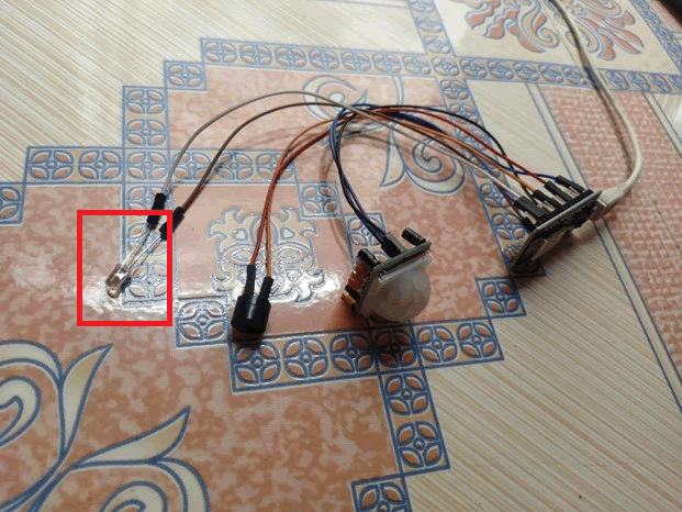
Figure 19: Status of the door that indicates it is in close state.
In conclusion, we have proposed an IoT-based security monitoring system for door access control. The system utilizes various components such as ESP32, ESP32-cam, PIR sensor, alarm buzzer, and an electric strike door lock to enable remote monitoring and control of the door. The system allows for detecting motion near the door, granting access to authorized individuals, logging door access history, receiving notifications for open doors, and activating alarms in case of forced entry.
Through simulations, we have validated the effectiveness of the system in accurately detecting movement within a certain range. We have also ensured the security of communication by encrypting messages using SSL encryption, protecting them from unauthorized access or tampering.
Additionally, we have presented the implementation of an interactive smart home security system that incorporates email alert functionality. The system is capable of sending alert emails to a designated Gmail account or any other email provider, providing real-time notifications to the homeowner.
There are several potential areas for future improvement and expansion of the proposed system. These include:
• Emergency call feature: Integration of an emergency call functionality that allows the system to directly contact the police or emergency services in case of a security breach or threat.
• Enhanced filtering and reporting: Implementing advanced filtering features to analyze and categorize the security reports generated by the system. This would provide more detailed insights and improve the overall effectiveness of the security monitoring.
• Two-way communication: Introducing a two-way communication feature between the door owner and guests. This could involve incorporating a voice or video communication system to facilitate direct interaction and verification before granting access.
• Integration with smart home ecosystem: Integrating the security system with other smart home devices and systems to create a comprehensive and interconnected home automation environment. This could include integration with smart locks, surveillance cameras, and voice assistants for seamless control and monitoring.
By addressing these future scopes, the proposed system can be further enhanced in terms of functionality, security, and user experience, making it an even more robust and effective solution for home security.
Citation: Mabasha S, Rao KS, Babu SR, Hameed SA (2025) Enhancing Home Security through an Android-based Door Security System Using IoT Technology. Adv Appl Sci Res. 16:56.
Copyright: © 2025 Mabasha S, et al. This is an open-access article distributed under the terms of the Creative Commons Attribution License, which permits unrestricted use, distribution, and reproduction in any medium, provided the original author and source are credited.